
Ducati Diavel Service Manual: Removal of the front brake master cylinder
Warning
The brake master cylinder manufacturer advises against servicing the brake master cylinder due to the safety critical nature of this component. Incorrect overhaul of these critical safety components can endanger rider and passenger safety.
Maintenance operations on these units are limited to renewal of the following parts: control lever, fluid reservoir assembly and relative fasteners and master cylinder fasteners.
Note
For the abs front braking system, also refer to sect. 7 - 5, Abs system operating information, sect. 7 - 6, System components, sect. 7 - 7, Abs components maintenance.
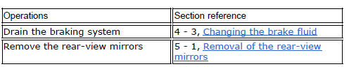
Undo the special screw (3), collect the sealing washers (4), and release the front brake master cylinder assembly (1) from the pipe.
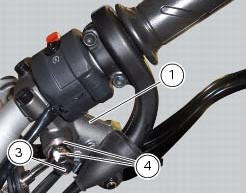
Loosen the screws securing the terminal (12) and then remove the front brake master cylinder assembly (1) from the handlebar.
For disassembly of components of the master cylinder assembly (1), refer to the exploded view at the beginning of this chapter.
 Front brake control
Front brake master cylinder
Brake lever
Special screw
Sealing washer
Screw
Phonic wheel
Brake disc
Pin
Left brake calliper
Boot
Bleed valve
Spare stand
Control unit - fr ...
 Refitting the front brake master cylinder
Insert the front brake master cylinder unit (1) on the right side of the
handlebar to bring the terminal internal edge in
correspondence to the bolted joints (a).
Fit the terminal (12) on the ...
Other materials:
Vehicle speed indicator
This function displays vehicle speed (km/h or mph depending on the set
measurement system).
The dashboard receives information about the actual speed and displays the
number increased by 5%.
Maximum speed displayed is 299 km/h (186 mph).
Over 299 km/h (186 mph) the display will show a s ...
Limitations
This emission control system warranty shall not cover any
of the following:
Repair or replacement required as a result of
Accident,
Misuse,
Repairs improperly performed or replacements improperly
installed,
Use of replacement parts or accessories not conforming
to ducati specifi ...
Vehicle pre-delivery
Transport packaging integrity check (if required);
Removal from the transport packaging (if required);
Motorcycle integrity check;
Check of the supplied kit completeness (refer to the parts list supplied
together with the bike packaging);
Only if the bike is supplied in a crate: handle ...