
Ducati Diavel Service Manual: Refitting the clutch master cylinder assembly
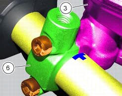
Insert the clutch master cylinder assembly (3) and the clamp (6) on the left handlebar, so that the top mating faces match the mark (z) on the handlebar as shown.
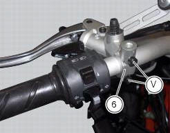
Couple terminal (6) to the clutch master cylinder control and fix them with the screws (v).
Tighten the retaining screws (v) to a torque of 10 nm +/- 10% (sect. 3 - 3, Frame torque settings) following the sequence 1-2-1 starting from the upper screw.
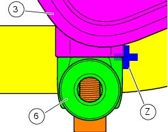
Locate the pipe (4) and seals (2) on the master cylinder assembly (3) and secure it with the special screw (1), without tightening it.
Warning
An incorrectly positioned hose can cause clutch faults and interfere with moving parts.
For the positioning of the clutch hose (4) and retaining clips, see the illustration at the end of this section.
Tighten the special screw (1) to the torque of 23 nm +/- 10% (sect. 3 - 3, Frame torque settings).

 Removal of the clutch master cylinder assembly
Warning
The clutch master cylinder manufacturer advises against servicing of
the clutch master cylinder (1) due to the safetycritical
nature of this component. Incorrect overhaul of this component ...
 Removal of the clutch transmission unit
Warning
The manufacturer of the clutch transmission unit (15) advises
against servicing of its internal parts due to the safetycritical
nature of this component.
Incorrect overhaul of these cri ...
Other materials:
Trip 2 meter
This function shows the distance travelled since the trip
meter was last reset (in km or miles depending on the
specific application).
Holding the button (1, fig. 14) ?
pressed for 3 seconds
when this function is displayed resets the trip meter.
When the reading exceeds 9999.9, Distance t ...
Changing the clutch fluid
Warning
Clutch fluid will damage painted surfaces if spilled on them. It is
also very harmful if it comes into contact with the skin or
with the eyes; in the event of accidental contact wash the affected area with
abundant running water.
Remove cover (1) and membrane from the clutch fluid res ...
Removal of the clutch master cylinder assembly
Warning
The clutch master cylinder manufacturer advises against servicing of
the clutch master cylinder (1) due to the safetycritical
nature of this component. Incorrect overhaul of this component could endanger
rider safety.
Maintenance operations of the master cylinder are limited to replac ...