
Ducati Diavel Service Manual: Refitting the cooling system hoses and unions
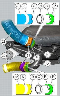
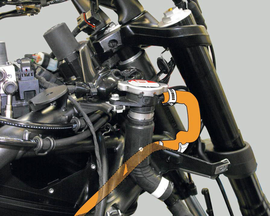
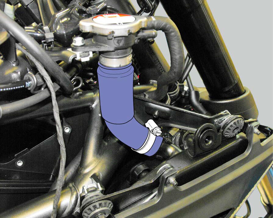
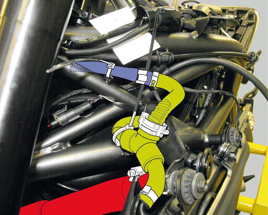
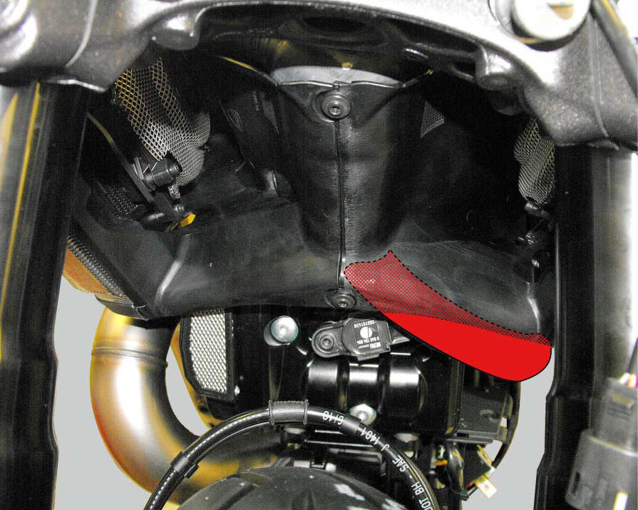
Position the pump/radiator sleeve (22) and the radiator/radiator sleeve (23).
Fit sleeve (23) and sleeve (22) to their corresponding fittings (n) and (o), and bring them fully home on collars (p).
Note
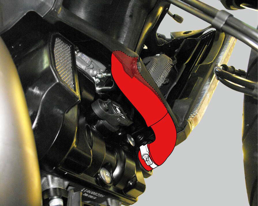
Sleeves (23) and (22) must be oriented so that the grooves (q) match the tabs (r) on fittings (n) and (o).
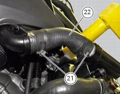
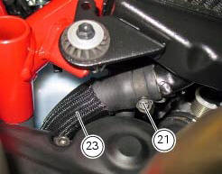
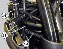
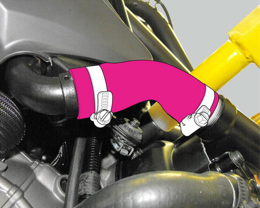
Insert the clip (21) on sleeve (23) and the clip (21) on sleeve (22), bringing them to the position of the white marks (s) on the sleeves.
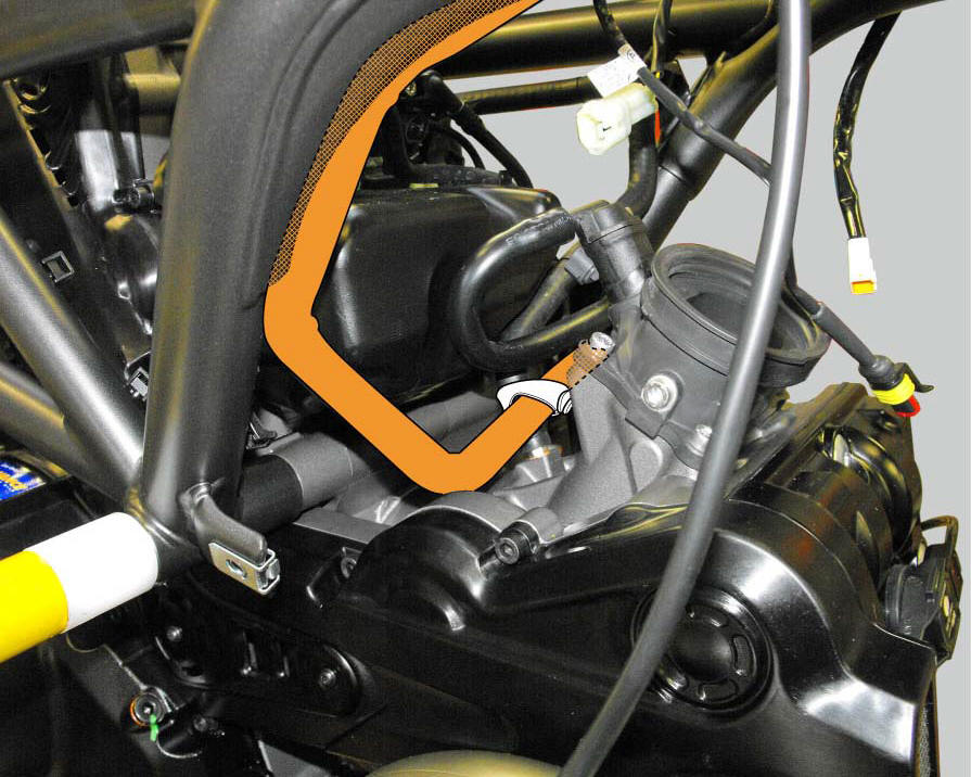
Orient the clamps (21) as shown and tighten them to a torque of 2.5 Nm +/- 10% (sect. 3 - 3, Frame torque settings).
Tighten the clamps (21) to a torque of 2.5 Nm +/- 10% (sect. 3 - 3, Frame torque settings).
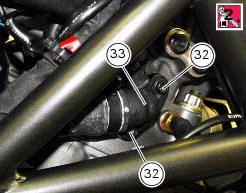
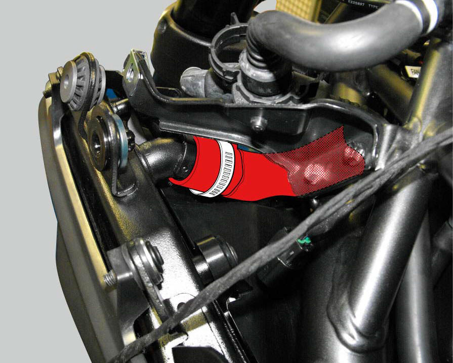
Install one gasket (31) into the seat of the vertical head fitting (33).
Fix the fitting (33) on the vertical head by means of the screws (32) with prescribed threadlocker, and tighten them to a torque of 6 nm (min. 5 Nm - max. 7 Nm) (sect. 3 - 3, Engine torque settings).
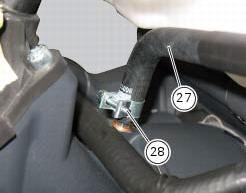
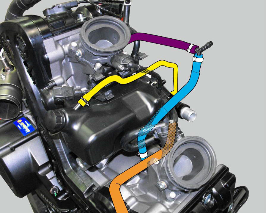
Place the breather pipe (27) on the half-casing fitting and tighten the clip (28).
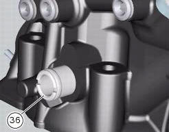
If removed, fit the coolant union (36) on the horizontal cylinder head and tighten it to a torque of 20 nm (min. 18 Nm - max. 22 Nm) (sect. 3 - 3, Frame torque settings).
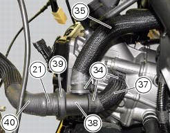
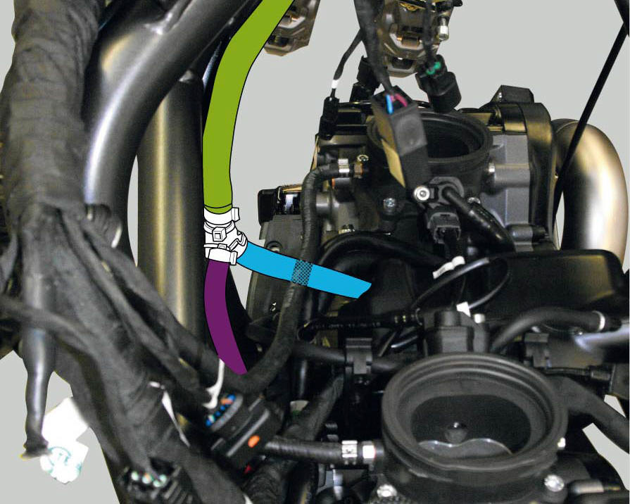
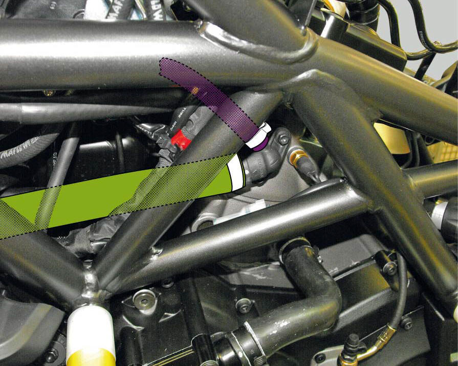
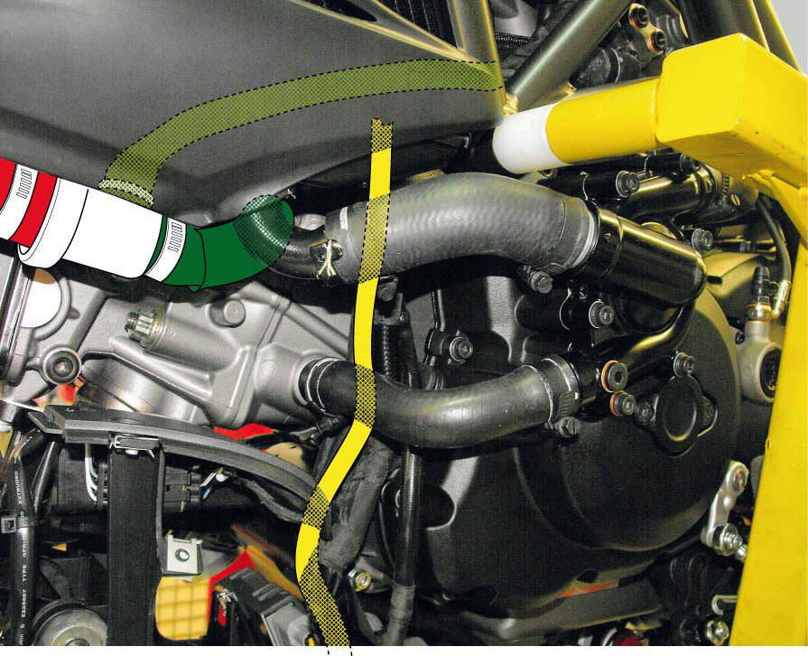
Assemble the thermostat (38) - thermostat/head sleeve (35) assembly by coupling and tightening them to a torque of 2.5 Nm +/- 10% (sect. 3 - 3, Frame torque settings) - and the thermostat/head sleeve (37) - radiator/thermostat sleeve (40) by tightening the clamps (21) and (34).
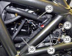
Place breather pipe (30) on the vertical head and tighten the clip (28) to a torque of 2.5 Nm +/- 10% (sect. 3 - 3, Frame torque settings).
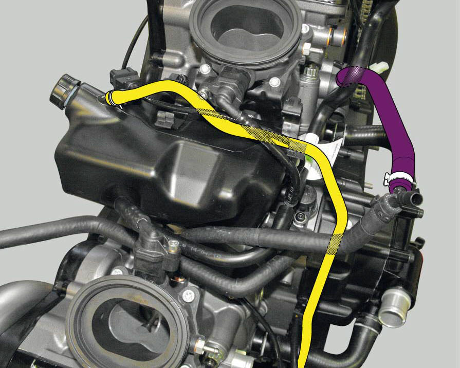
Fit the clamp (34) on the union (33) matching to dots.
Position the thermostat unit (38) - thermostat/head sleeve (35) - thermostat/head sleeve (37) with the clips (34) and tighten the clips (34) to a torque of 2.5 Nm +/- 10% (sec. 3 - 3, Frame torque settings).
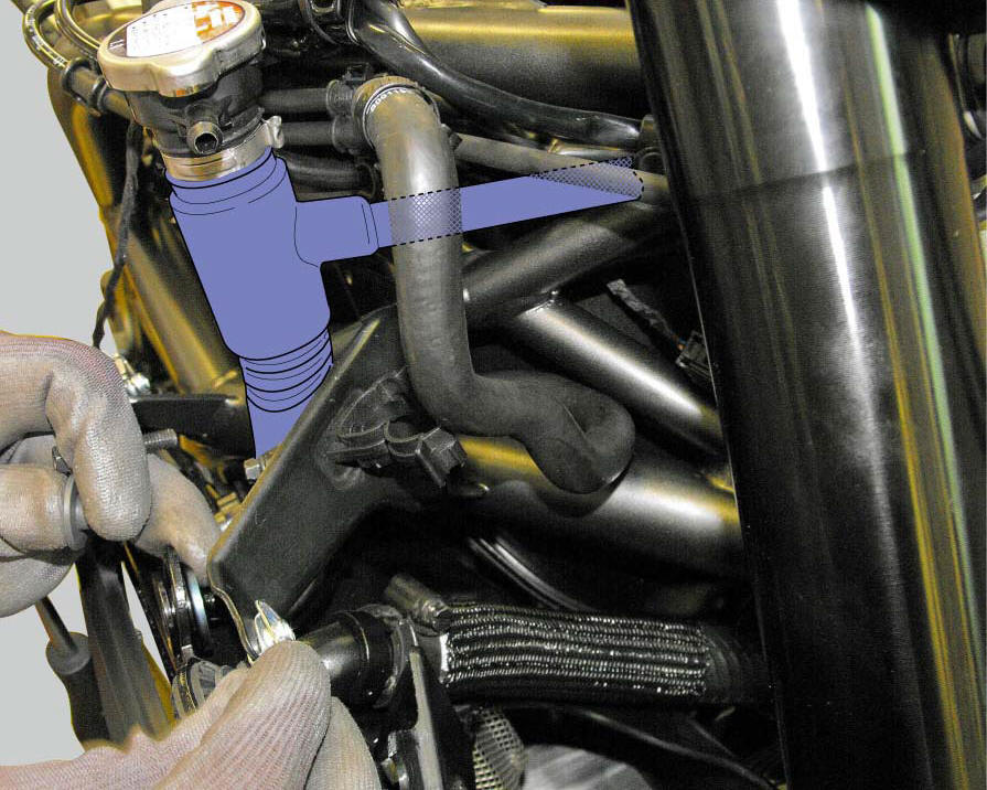
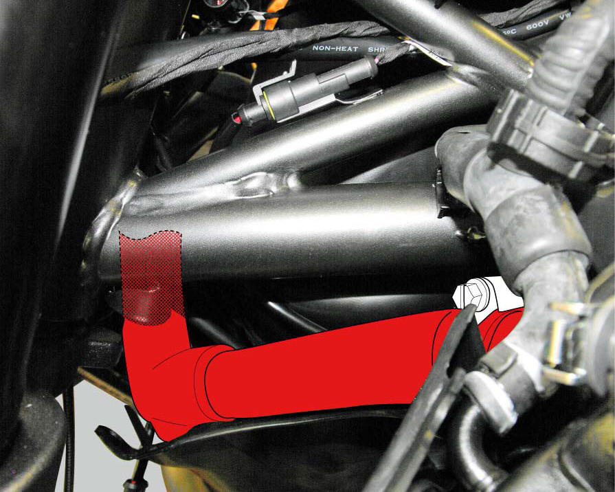
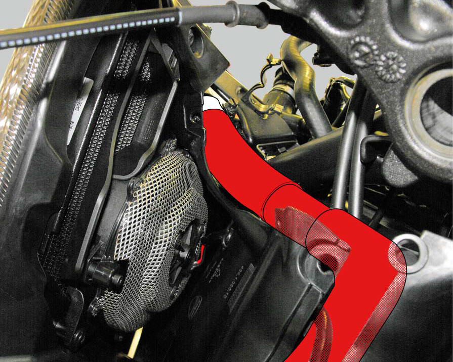
Fix the breather pipe (26) to the radiator/plug sleeve (24) and to the left radiator by tightening the clips (25) and (43) to a torque of 1 +/- 10% (sect. 3 - 3, Frame torque settings).
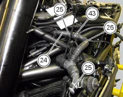
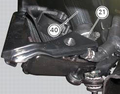
Position the radiator/thermostat sleeve (40) with the clips (21) and the radiator/plug sleeve (24) on the radiators and tighten the clips to a torque of 2.5 +/- 10% (Sect. 3 - 3, Frame torque settings).
Positioning the cooling system tubes
 Removal of the cooling system hoses and unions
Loosen the clips (21) that secure the radiator/thermostat sleeve (40) and the
radiator/plug sleeve (24) to the water
radiators.
Loosen clips (25) and (43) that secure the breather pipe ...
 Water radiators
Clip nut
Spacer
Vibration damper mount
Screw
Screw
Spacer
Vibration damper mount
Clip nut
Bush
Spacer
Rear sprocket
Screw
Water radiator (right)
Screw
Screw
Air de ...
Other materials:
Rectifier-regulator
The rectifier (1) is placed in the electrical components compartment.
The rectifier/regulator consists of an aluminium casing containing the diodes
that rectify the current produced by the
alternator. It also contains an electronic device that regulates the current
supplied by the alternator ...
Checking valve clearances
To check the valves clearance, it is necessary to have access to the cylinder
head covers and then remove the
components listed below.
Unscrew the two fixing screws (1) of the cover (2) according to the
crankshaft.
Fit the tool handgrip 88713.0123 In the holes of the generator cover t ...
Lubricating cables and joints
Check the outer sheath of the throttle control and cold start
lever cables for damage at regular intervals. The outer plastic
cover should not be flattened or cracked. Operate the
controls to make sure the inner cables slide smoothly inside
the outer sheath: if you feel any friction or catching, ...