
Ducati Diavel Service Manual: Coolant expansion tank
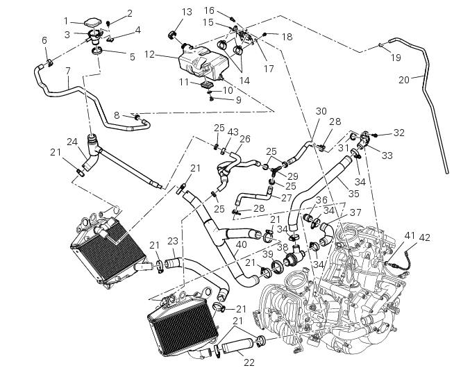
- Plug
- Screw
- Fuel filler flange
- Clip nut
- Clamp
- Hose clip
- Valve/tank hose
- Clamp
- Screw
- Spacer
- Rubber mounting
- Expansion reservoir
- Filler cap
- Hose clip
- Support
- Screw
- Washer
- Screw
- Hose clip
- Breather hose
- Clamp
- Pump/radiator sleeve
- Radiator/radiator sleeve
- Radiator/plug sleeve
- Clamp
- Breather pipe (front)
- Breather pipe (lower)
- Hose clip
- Y-fitting
- Breather pipe (rear)
- O-ring
- Screw
- Water outlet fitting (vertical)
- Clamp
- Thermostat/cylinder head sleeve (vertical)
- Fuel filler flange
- Thermostat/cylinder head sleeve (horizontal)
- Thermostat
- Thermostat protection ring
- Radiator/thermost. Sleeve
- Copper gasket
- Temperature sensor
- Clamp
Spare parts catalogue
Diavel abs cooling system
Diavel abs expansion reservoir
Diavel carbon abs cooling system
Diavel carbon abs expansion reservoir
Important
Bold reference numbers in this section identify parts not shown in the figures alongside the text, but which can be found in the exploded view diagram.
- Removal of the expansion tank
- Refitting the expansion tank
- Removal of the cooling system hoses and unions
- Refitting the cooling system hoses and unions
 Cooling system
...
 Removal of the expansion tank
Loosen the clamp (6), open the hose guide (a) and slide the hose (7) out of
the radiator.
Open clamps (14) and release the hoses that pass through them.
Loosen the screws (16).
Remove ...
Other materials:
Refitting the front sprocket
Grease the o-ring (16) and install it on the front sprocket spacer (15).
Fit the spacer, from the o-ring side, on the secondary shaft and drive it fully
home against the inner ring of the bearing.
Check that the splines of the gearbox secondary shaft and the sprocket are in
perfect condi ...
Start procedure with pin code (no keys)
The motorcycle may be started without keys with a special procedure using the
dashboard and the switches on the
handlebar.
Note
This procedure is only possible if the pin code has been enabled
previously. For security reasons, the pin code is disabled
by default when the vehicle leaves the f ...
Battery voltage indicator (battery)
This function describes the battery voltage indicator.
To access the function it is necessary to view the "setting" menu page 48, using
button (1, fig. 14) ?"" or (2, fig.
14) ?" " select the "battery" function
and press the reset
button (12, fig. 12 ...