
Ducati Diavel Service Manual: Removal of the camshafts
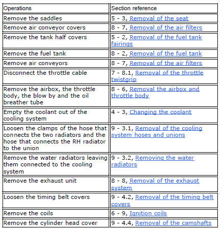
Unscrew and remove the screws (7) and the o-rings (8) from the cylinder head covers.
Remove the cylinder head cover (6).
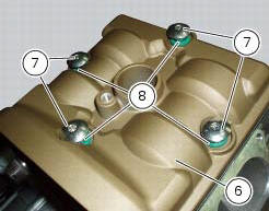
Remove the gaskets (4) and (9).
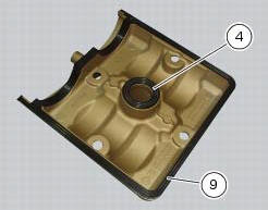
Repeat the same procedure for the other cylinder head cover. Unscrew the screws (3) securing the camshaft supports.
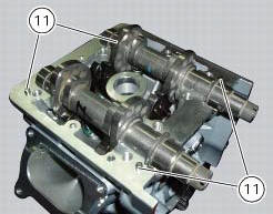
Withdraw the camshaft supports (22) and (23) straight out from the cylinder head, taking care not to damage the machined faces and locating dowels (11).
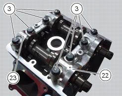
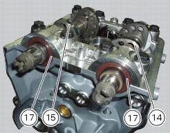
Remove the exhaust camshaft (14) and the intake camshaft (15), and slide off the sealing rings (17) on their ends.
Repeat the same procedure for the other cylinder head.
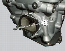
If necessary, unscrew the stud bolts (2) from the cylinder heads.
 Camshafts
Head
Stud bolt
Special screw
Sealing washer
Horizontal cylinder head cover
Vertical cylinder head cover
Special screw
O-ring
Head gasket
Screw
Pin
Union
Clamp
Horizont ...
 Checking the camshafts and supports
Check the cam contact surfaces for scratches, grooves, steps and waving.
Worn cams are frequently the cause of poor timing, which leads to loss of engine
power.
Place the camshaft between two ...
Other materials:
Keys (fig. 62)
The owner receives a set of keys comprising:
1 Active key (1, fig. 62)
1 Passive key (2, fig. 62)
It contains the code used by the "hands free" system for the
key-on, in different modes.
The active key (1, fig. 63) Is the one that is normally used:
press button (a, fig. 63) To ...
Removing the silencer
Loosen the clamp (38) that retains the silencer (4) to the complete exhaust
system.
While holding the nut (8), loosen the screw (1) and remove the silencer (4)
from the motorcycle.
Loosen the screws (40) and remove the silencer guard (41).
...
Renewal of the headlight
Disconnect the headlight connectors (a) from the main wiring (refer to the
tables of paragraph "routing of wiring on
frame", sect. 6 - 1).
Loosen nuts (2) that fix the front optical unit to the bottom yoke, and
recover the washers (3).
Remove the complete front optical unit by sliding ...