
Ducati Diavel Service Manual: Refitting the timing covers
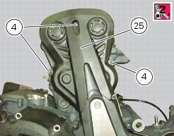
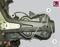
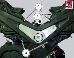
Locate vertical cylinder external cover (25), horizontal cylinder external cover (3) and central external cover (1) by starting the screws (4).
Apply the recommended threadlocker to the screws (4).
Tighten the screws (4) to a torque of 10 nm (min. 9 Nm - max. 11 Nm) (sect. 3 - 3, Engine torque settings).
Note
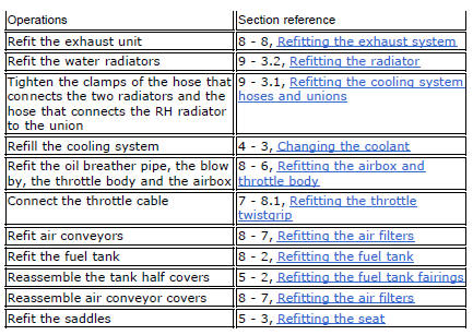
If the above operations have been carried out with the engine installed in the frame, refit the previously removed parts.
 Refitting the timing belts
Rotate the pulleys on the timing belt driveshaft until the timing mark on the
outer roller is aligned with the mark on the
clutch-side crankcase cover.
In this condition, the horizontal cylinder ...
 Camshafts
Head
Stud bolt
Special screw
Sealing washer
Horizontal cylinder head cover
Vertical cylinder head cover
Special screw
O-ring
Head gasket
Screw
Pin
Union
Clamp
Horizont ...
Other materials:
Refitting the front mudguard
Warning
Do not use the motorcycle without the front mudguard fitted to avoid
the risk of the brake pipes fouling the wheel on
braking.
Insert the screws (5) in spacers (6) with recommended threadlocker, as shown
in the figure.
Position the front mudguard (1) and start the special screws (5 ...
The hands free relay
Introduction
This relay provides key on +15 power to all the devices on the motorcycle.
Functionally, it replaces the conventional
ignition switch.
Wiring diagram
The hands free relay receives +12 volt power directly from the battery via
the main 30 a fuse. Hands free - 3: pin 3 on
hand ...
Disassembly of the rear brake control
The brake master cylinder is supplied only as a complete unit; internal
components cannot be replaced.
To disassemble the master cylinder's outer parts, follow the indications given
in the exploded view at the beginning of this
section.
If the bush (10) inside the brake pedal (6) needs to ...