
Ducati Diavel Service Manual: Refitting the intake manifold and coolant union
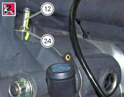
Apply prescribed threadlocker to the fitting (12), start it with seal (24) and tighten it to a torque of 2.5 Nm (min. 2 Nm - max. 3 Nm) (sect. 3 - 3, Frame torque settings).
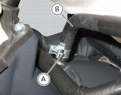
Install the pipe (b) and tighten the clamp (a) to the torque of 1 nm +/- 10% (sect. 3 - 3, Engine torque settings).
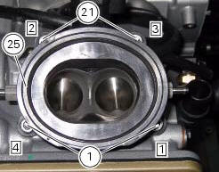
Check that the mating surfaces of the cylinder head and manifold are perfectly flat and clean and install the intake manifold (25) on the cylinder head.
Lock the fixing screws (21) to the torque of 10 nm (min. 9 Nm - max. 11 Nm) (sect. 3 - 3, Engine torque settings) in a cross-pattern sequence (1-2-3-4).
 Removal of the intake manifold and coolant union
Loosen the clips (f) and remove the hoses (t).
Remove the manifolds (25) undoing the screws (21).
Loosen the clamp (a) and remove the hose (b). Remove the union (12) and
recove ...
 Valves - rocker arms
Closing rocker arm shaft
Opening rocker arm shaft
Opening rocker arm
Closing rocker arm (left)
Valve opening shim
Half rings
Valve closing shim
Sealing ring
Valve guide
Exhaus ...
Other materials:
Refitting the front sprocket
Grease the o-ring (16) and install it on the front sprocket spacer (15).
Fit the spacer, from the o-ring side, on the secondary shaft and drive it fully
home against the inner ring of the bearing.
Check that the splines of the gearbox secondary shaft and the sprocket are in
perfect condi ...
Refitting the timing gears
Before reassembling the removed parts, check timing gears (13) for wear.
Change, if necessary.
Important
The timing gears (13) must always be renewed as a pair.
Refitting is the reverse of removal.
Warning
When introducing the driven gear (b) check that the tongue (15) is
correctly fitted o ...
Riding mode customisation
This function customises each riding style.
To access the function it is necessary to view the ""setting" menu", using
buttons (1) "s" or (2) "t" select the "riding
mode" function and press the reset button (3) to enter the following page.
When accessing the function, the three riding modes ...