
Ducati Diavel Service Manual: Refitting the side stand
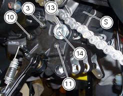
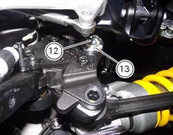
Place the stand plate on the rear shock absorber support; bring adjuster (14) in line with bracket (s) and start the screw (12) in the nut behind the bracket (s).
Insert the screws (11), (3) and (10) fully home in this order, but do not tighten.
Loosen the screw (12) with the relative nut, tighten the adjuster (14) to a torque of 0.6 Nm +/- 10% (sect. 3 - 3, Frame torque settings) and tighten the screw (12) to a torque of 2 nm +/- 10% (sect. 3 - 3, Frame torque settings) while holding the nut.
Locate service tool no. 88713.3166 On the ring nut (13) and fit the torque wrench to the tool. While holding the adjuster (14), tighten the ring nut (13) to a torque of 100 nm +/- 5% (sect. 3 - 3, Frame torque settings).
Tighten screws (11), (3) and (10) in this order to a torque of 44 nm +/- 10% (sect. 3 - 3, Frame torque settings).
Finally, tighten the screw (12) to a torque of 45 nm +/- 10% (sect. 3 - 3, Frame torque settings) while holding the nut.
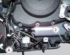
Connect connector (a) of the side stand switch to the main wiring harness.
To place the stand switch wiring refer to the table (sect. 6 - 1, Routing of wiring on frame).
 Removing of the side stand
Disconnect connector (a) of the stand switch (2) from the main wiring.
Loosen the screws (3), (10), (11) and (12) securing the stand bracket (4) to
the engine and remove the complete side
...
 Frame inspection
Frame
Rh subframe
Lh subframe
Grub screw
Nut
Special screw
Rubber pad
Nut
Special screw
Screw
Left-hand bracket
Hose clip
Hose clip
Right-hand bracket
Special screw
...
Other materials:
Riding style function (riding style change)
This function changes the motorcycle riding style.
Each riding style is associated with a different intervention
level of the traction control (dtc - ducati traction control)
and different engine power and output.
To change the motorcycle riding mode, press the reset
button once (12, fig. 1 ...
Removing of the front sprocket
Undo the screws (11) and remove the chain cover (10).
Loosen the chain (sect. 4 - 3, Adjusting the chain tension).
Remove the chain with the tool code 88713.1344.
The tool is composed of a holder (a), punch (b), body (c) and two wrenches (d)
and (e).
Fit the link to be opened into th ...
Noise and exhaust emission control
system information
Source of emissions
The combustion process produces carbon monoxide and
hydrocarbons. Control of hydrocarbons is very important
because under certain conditions, they react to form
photochemical smog when subjected to sunlight.
Carbon monoxide does not react in the same way, but is
toxic. Duca ...