
Ducati Diavel Service Manual: Removing of the side stand
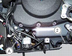
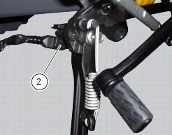
Disconnect connector (a) of the stand switch (2) from the main wiring.
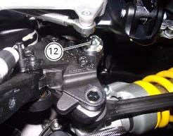
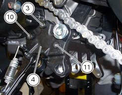
Loosen the screws (3), (10), (11) and (12) securing the stand bracket (4) to the engine and remove the complete side stand assembly.
Disassembly of the side stand
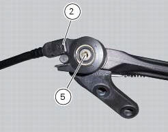
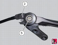
Undo the fixing screw (5) and remove the side stand switch (2).
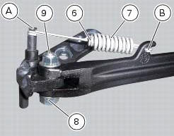
Release the side stand return springs (6) and (7) of the fasteners (a) and (b).
Undo the stand fixing pin (9) to the bracket and remove the side stand (1) and the nut (8).
Inspecting the side stand
Fit the side stand leg to the bracket and check that there is no excessive clearance. Ensure that the ends of the side stand are not bent with respect to the shank.
A side stand which shows signs of cracking must be renewed immediately.
To check the switch (2) refer to sec. 6 - 6, Checking the side stand switch.
Reassembling of the side stand
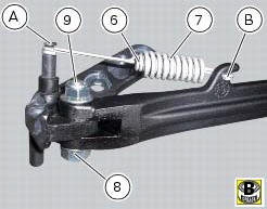
Insert the side stand (1), properly greased, in the bracket (4) and fix it with the pivot (9) and the nut (8).
Tighten the nut (8) to the torque of 20 nm +/- 10% (sect. 3 - 3, Frame torque settings).
Position the side stand return springs (6) and (7) and fix them to the fasteners (a) and (b) on the bracket and on the stand.
Set switch (2) to plate (4) by inserting sensor pin (c) into side stand hole (d) and making sure side stand pin (e) matches with groove (f) on sensor.
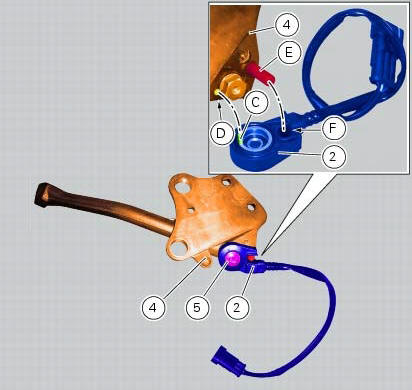
Fit the retaining screw (5) with recommended threadlocker and tighten it to a torque of 5 nm +/- 10% (sect. 3 - 3, Frame torque settings).
 Stands
Side stand
Side stand switch
Screw
Plate
Screw
Inner spring
Outer spring
Nut
Rotation pivot
Screw
Screw
Screw
Nut
Clearance adjuster
Spare parts catalogue
Diavel a ...
 Refitting the side stand
Place the stand plate on the rear shock absorber support; bring adjuster (14)
in line with bracket (s) and start the screw
(12) in the nut behind the bracket (s).
Insert the screws (11), (3) and ...
Other materials:
Technical specifications
General
Colours
Transmission
Timing system/valves
Crankshaft
Cylinder/piston
Gearbox
Cooling system
Front wheel
Front suspension (diavel abs)
Front suspension (diavel carbon abs)
Rear wheel
Rear suspension (diavel abs)
Rear suspensio ...
Removal of the crankshaft/connecting rods assembly
After separating the crankcase halves, withdraw the crankshaft (6) complete
with connecting rods (2).
...
How to turn the motorcycle off
To turn the motorcycle off, turn the switch from "run on" to "run off". The
engine stops. To switch the dashboard off,
push the on/off switch downwards. When released, the switch automatically
returns to the "run off" position.
Push the switch downwards to switch the engine off and enter " ...