
Ducati Diavel Service Manual: Removal of the gearbox assembly
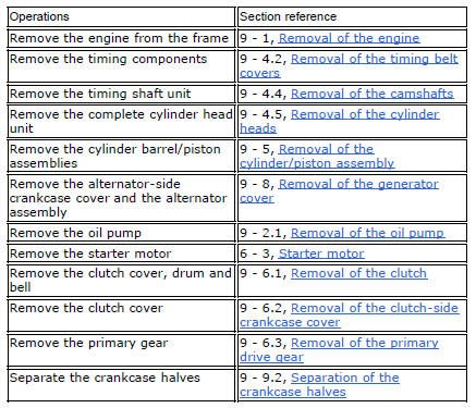
Withdraw the selector fork shafts (30).
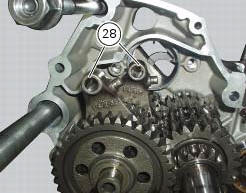
Move the forks (28) and (29) to disengage them from the slots in the selector drum (14).
Withdraw the selector drum (16) taking care not to lose shims (31) and (27) mounted on the shaft. Note that the positions of the shims must not be inverted.

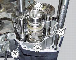
Once removed, it is possible to replace the special rollers (13).
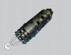
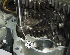
Remove gear selector forks (29) and (28).
Remove
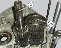
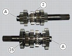
Remove the gearbox primary (2) and secondary (25) shafts complete with gears, taking care to recover the spacers on the ends of the shafts.
If the bearing inner rings (a) are left on the shafts, slide them off the ends of the gearbox primary (2) and secondary (25) shafts (sect. 9 - 9.2, Separation of the crankcase halves).
 Gearbox shafts
Shim, thickness 1
Gearbox primary shaft
Shim, thickness 0.5
Needle roller bearing
5Th speed driving gear
Splined washer, thickness 0.5
Circlip
3Rd- 4th speed driving gear
6Th sp ...
 Disassembly of the gearbox shafts
Place the shaft in a vice in such a way as to facilitate the disassembly
operations.
Important
Take care not to invert the positions of the shims on reassembly:
this would potentially lead to jam ...
Other materials:
Refitting the radiator
The reassembly procedure is the same for both radiators.
Check for the nuts with clips (8).
Refit the rh radiator (13) on the frame and tighten the screws (4) and (5)
with the spacers (6) to a torque of 10 nm
+/-10% (sect. 3 - 3, Frame torque settings).
Connect the connections of ...
Adjusting the rear shock absorber
The rear shock absorber has external commands that enable
you to adjust the setting to suit the load on the motorcycle.
The adjuster (1, fig. 111) Located on the lower connection
holding the shock absorber to the swingarm adjusts the
damping during the rebound phase (return).
The knob (2, f ...
Overhauling the rear swingarm
Inside the swingarm (8), in correspondence with the pivot point on the frame,
there is a pair of ball bearings (10) and a
spacer (11) on the rh side, and a pair of roller bearings (6), with sealing
rings (5), on the lh side.
To change the bearings, proceed as follows.
Remove the shims ( ...