
Ducati Diavel Service Manual: Disassembly of the gearbox shafts
Place the shaft in a vice in such a way as to facilitate the disassembly operations.
Important
Take care not to invert the positions of the shims on reassembly: this would potentially lead to jamming when using the gear selector control, making it necessary to reopen the engine crankcase.
Disassembly of the gearbox secondary shaft
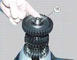
Remove the chain-side shim washer (26) and clutch-side shim washer (15) from the secondary shaft.
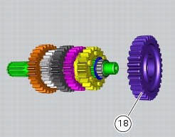
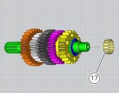
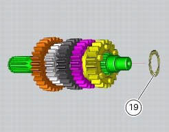
Withdraw the first speed driven gear (18) with the roller cage (17) and the shim (19).
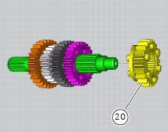
Remove the fifth speed driven gear (20).
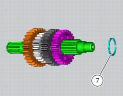
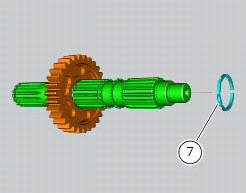
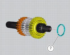
Use two flat blade screwdrivers to remove the circlip (7) taking care not to damage the shaft surface.
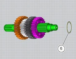
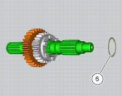
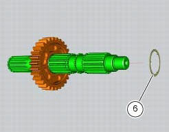
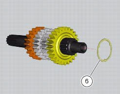
Remove the circlip (7) and the splined washer (6).
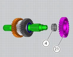
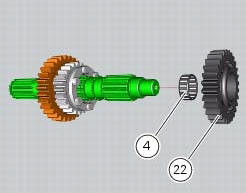
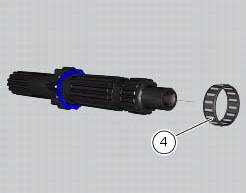
Withdraw the fourth speed driven gear (21) with the roller cage (4) and splined washer (12).
Remove the
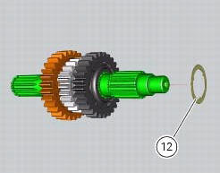
Remove the third speed driven gear (22) with the roller cage (4) and the splined washer (6).
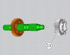
Remove the circlip (7) and remove the sixth speed driven gear (23).
Remove
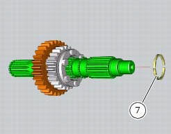
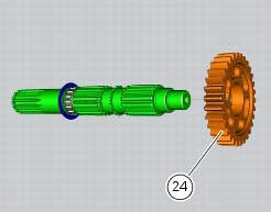
Remove the circlip (7) and withdraw the splined washer (6) and the second speed driven gear (24).
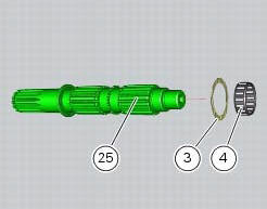
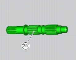
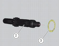
Withdraw the roller cage (4) and the shim (3). All the components have thus been removed from gearbox secondary shaft (25).
Disassembly of the gearbox primary shaft
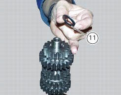
Remove the chain-side shim washer (11) and the clutch-side shim washer (1) from the primary shaft.
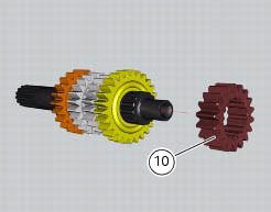
Remove the second speed driving gear (10). Use two screwdrivers to prise out the circlip (7) and the splined washer (6).
Important
Take care to avoid damaging the surface of the shaft while removing circlip (7).
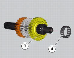
Remove the sixth speed driving gear (9) with its roller cage (4). Remove the splined washer (6) and the circlip (7).

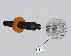
Withdraw the third and fourth speed driving gear (8).
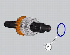
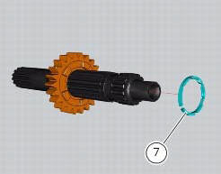
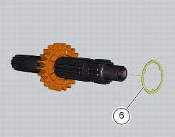
Remove the circlip (7) and the splined washer (6).
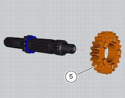
Remove the fifth speed driving gear (5) with the roller cage (4).
Slide the shim (3) off the primary shaft (2).
 Removal of the gearbox assembly
Withdraw the selector fork shafts (30).
Move the forks (28) and (29) to disengage them from the slots in the selector
drum (14).
Withdraw the selector drum (16) taking care not to lose s ...
 Overhaul of the gearbox
Check the condition of the front coupling dogs of the gears. They must be in
perfect condition and with no sign of wear on
the edges of the teeth.
The idler gears must rotate freely on their sha ...
Other materials:
Reassembly of structural components and the frame
Check for the nuts with clips (8).
Apply recommended grease on the threads of the adjusters (4) and the ring
nuts (5) having care not to have grease on
the surface (c) of the adjusters.
Tighten the adjusters on the ring nut side opposite to that featuring flats
until bringing the surfac ...
Background setting function for the instrument panel on tank - dashboard 1
This function allows setting the "background" of the
instrument panel on tank.
To access the function it is necessary to view the "setting" menu page 48, using
button (1, fig. 14) ?"
" or (2, fig. 14) ?" " select the "back light" function
a ...
Indicator cons. - Instantaneous fuel consumption
This function indicates the "instantaneous" fuel consumption.
The calculation is made considering the quantity of fuel used
and the distance travelled during the last second. The datum is
expressed in "l/100" (litres / 100 km); it is possible to change
the units of measurem ...