
Ducati Diavel Service Manual: Removing the valve rocker arms
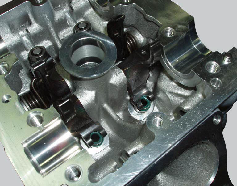
With the cylinder head in the condition described in the previous paragraph, remove the rocker arms.
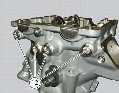
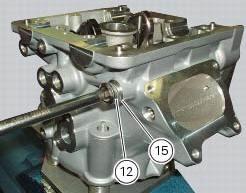
Unscrew the eight plugs (12) and recover the seals (15).
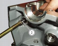
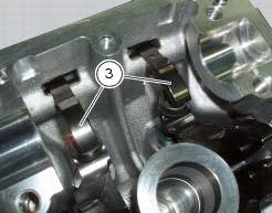
Using an m6 screw, withdraw the shafts (2) of the opening rocker arms (3) on the exhaust and intake sides.
Remove the opening rocker arms (3).
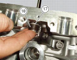
Using the claw of the rocker arm spring tensioning kit 88713.2069 Installed between the spring and the inner wall of the cylinder head, move the straight end of the rocker arm return spring (19) and (18) and insert it in the drilled shaft.
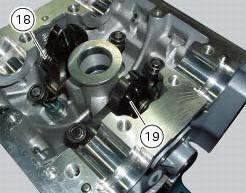
Use the shaft to slide the end of the spring into its final position.
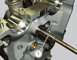
Using an m6 screw, withdraw the shafts (1) of the closing rocker arms on the exhaust and intake sides.
Remove the closing rocker arms (4) and (16), the springs (18) and (19) with the spacers (17).
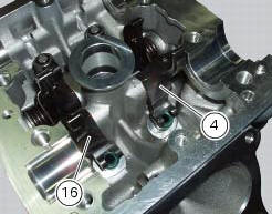
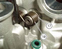
Carry out the same operation to remove the closing rocker arms (4) and (16), the springs (24) and (25) with the spacers (23).
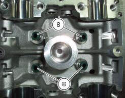
Remove the sealing rings (8) from the ends of the valve guides.
Repeat the same procedure for the other cylinder head.
 Removing the valves
Raise the rocker arm (3) and remove the opening shim (5) from the valves with
a pair of pliers.
Push down the closing rocker arms (16) and (4) and the closing shim (7).
Remove the half r ...
 Overhaul of cylinder head components
Cylinder heads
Remove any carbon deposits from the combustion chamber and its ducts.
Remove any scale from the coolant ducts.
Check for cracking and inspect the sealing surfaces for scoring, ri ...
Other materials:
Air temperature sensor
Introduction
The engine control system on the diavel uses a sensor that measures air
temperature. This sensor has a resistance of
ntc type (negative temperature coefficient), that reduces its own value when the
temperature increases. The air
temperature sensor allows the engine control unit t ...
Reassembly of rear shock absorber - rocker arm - linkage assembly
Once the needle roller bearings (9) have been removed from the rocker arm
(18), upon reassembly fit a new needle roller
bearing (9) on drift part no. 88713.1071 And lubricate with recommended grease.
Support the rocker arm and drive the needle roller bearings into the rocker arm
bore until t ...
Removal of the clutch-side crankcase cover
Unscrew the screws (2), (3) and (5) securing the clutch-side crankcase cover
(1).
Tap around the edge of the cover with a plastic mallet to detach it from the
crankcase half.
Remove the clutch cover (1) paying attention to the centring bushing (12).
Check the condition of the cent ...