
Ducati Diavel Service Manual: Reassembly of the crankcase halves
The crankcase halves must be in good condition and perfectly clean. The mating surfaces must be perfectly flat and free from burrs.
Overhauling the alternator-side crankcase half
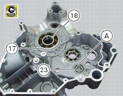
The following parts must be present on the internal side of the crankcase half:
- Gearbox secondary shaft bearing (23): apply grease to the bearing rollers. Fit the inner race (a) removed previously from the bearing. Apply grease to the inner ring;
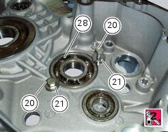
- The primary shaft bearing (28), secured with screws (20) and retaining spacer (21): apply prescribed threadlocker to the screws (20) and tighten them to a torque of 10 nm (min. 9 Nm - max. 11 Nm) (sect. 3 - 3, Engine torque settings);
- The main bearing (18) with the corresponding bushing (17) (if present).
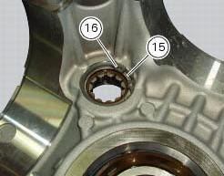
The roller bearing (15) with retaining circlip (16) installed in correspondence with the end of the timing belt driveshaft.
Insert the circlip (5) in the crankcase half installing it in its seat on the bearing (4).
Refitting the alternator-side crankcase half
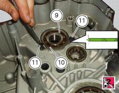
The following parts must be present on the internal side of the crankcase half: the double race ball bearing (9) supporting the selector fork shaft. Apply threadlocker to the screws (11). Fit the retaining plate (10) to the gearbox secondary shaft bearing (9) screwing the screws fully into the chain-side crankcase half (11).
Note
The bearing retaining plate must be positioned so that the countersunk side is facing upwards.
Tighten the screws (11) to a torque of 10 nm (min. 9 Nm - max. 11 Nm) (sect. 3 - 3, Engine torque settings).
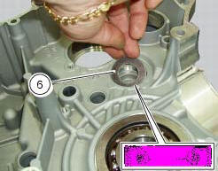
Lubricate the ring (6) with denatured alcohol, drive it fully home against the crankcase half, and orient it as shown.
The primary shaft bearing (7) with internal spacer (6), oriented so that the closed side of the plastic roller cage (m) faces The crankcase half: apply grease to the bearing rollers. Fit the inner race (a) removed previously from the bearing. Apply grease to the inner race.
The main bearing (1) with the corresponding bushing (2) (if present).
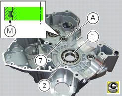
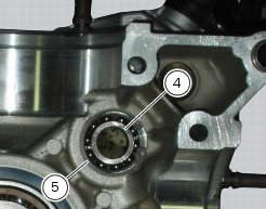
The bearing (4) with the retaining circlip (5) installed in correspondence with the timing belt driveshaft.
Insert the circlip (5) in the crankcase half installing it in its seat in the crankcase half on the bearing (4).
Note
Bearings do not have a specific mounting position (except main bearings); however it is good practice to install the bearings so that side bearing the writing is facing upwards.
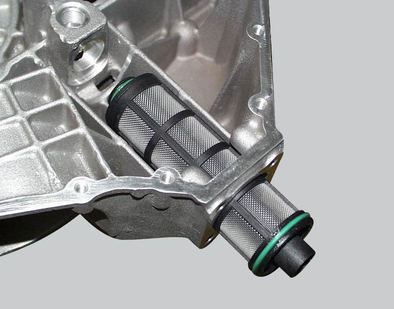
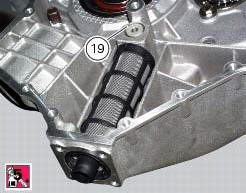
Fit the mesh filter as described in sect. 4 - 3, Changing the engine oil and filter cartridge.
Important
To avoid damaging the filter, insert it by hand only. Do not use hammers or other metal tools.
Above the mesh filter seat there is a plug (19) which closes off the lubrication oilway. If it is to be renewed, apply the prescribed threadlocker to its threads.
Tighten the plug to a torque of 24 nm (min. 21 Nm - max. 27 Nm) (sect. 3 - 3, Engine torque settings).
 Main bearings
The main bearings have are of the angular contact type with offset inner
races so that the balls transmit loads from one
groove to the other along straight lines at an angle to the axis of the bear ...
 Shimming the shafts
Before assembling the crankcase halves, calculate the shims required to
obtain the correct end float of the crankshaft and
gearbox shafts.
To determine the correct shim thickness proceed as foll ...
Other materials:
Clock setting function
This function sets the clock.
To access the function it is necessary to view the ""setting" menu", using
buttons (1) "s" or (2) "t" select the "clock"
function and press the reset button (3) to confirm.
In the following screen the message "setting" is highlighted in green (4); now,
press ...
Units of measurement modification function
This function allows you to change the units of measurement
of the displayed values.
To access the function it is necessary to view the "setting" menu page 48, using
button (1, fig. 14) ?"" or (2, fig.
14) ?" " select the "set units" function
and pre ...
Useful information for safe riding
Warning
Read this section before riding your motorcycle.
Many accidents are the result of the inexperience of the
rider. Always make sure you have your licence with you; you
need a valid licence that entitles you to ride a motorcycle.
Do not lend your motorcycle to persons who are
inexperie ...