
Ducati Diavel Service Manual: Reassembly of the connecting rods
Before starting, check that the crankshaft main bearing journals and big-end journals are free of burrs or evident signs of machining: if necessary, clean the surfaces with very fine emery cloth and oil.
Check that the grooves are in perfect condition with no signs of forcing.
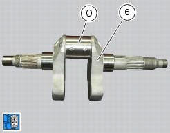
Clean the crank pin (o) on the crankshaft (6) thoroughly and lubricate.
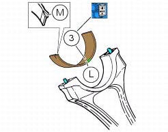
Take the bearings (3) necessary to shaft/connecting rod coupling, following the indications provided (sect. 3 - 1.1, Cylinder/piston).
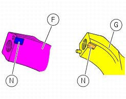
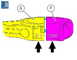
Insert the bearings in the connecting rod seats matching the tooth (m) of the bearings with the corresponding marks (n) on the connecting rod cap (f) and on the connecting rod small end (g). It is essential that the tooth (m) adheres perfectly with its own mark (n).
Warning
In the case of blue and yellow bearing coupling, fit the yellow on the connecting rod and the blue on the connecting rod cap.
Lubricate the bearing (3) fitted on the connecting rod small end.
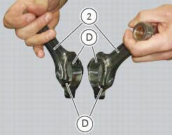
Check that each connecting rod (2) and cap are fitted with their locating pins (d).
Wash the pins and dry them with compressed air.
Fit the connecting rod on the crankshaft, in the same position in which it was removed.
Insert the connecting rod in the crankshaft, so that the centring pins face the internal side.
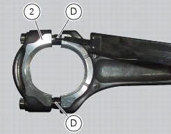
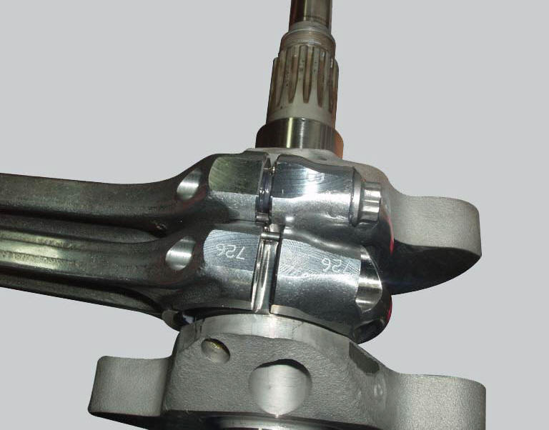
Join the connecting rod cap (f) with the corresponding connecting rod small end (g), checking that the progressive number stamped on the two pieces is the same, as shown in the figure.
Important
Check that the progressive numbers of a connecting rod are next to the selection of the other connecting rod.
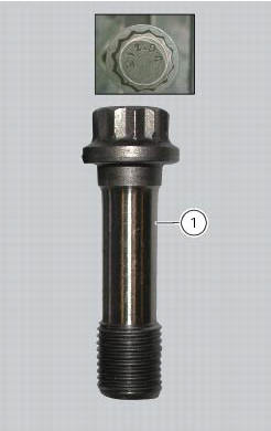
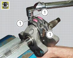
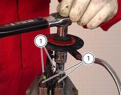
Fill the recommended grease into the two ends of the hole to lubricate threads and underside of the new screws (1) and the thread of the shaft.
Warning
The grease utilised is an irritant in contact with the skin. Wear protective gloves.
Important
Lubrication of big-end cap screws is essential to obtain the correct coupling and to prevent breakage of the parts.
The big-end cap screws may only be used for one tightening.
Tighten the screws (1) by hand.
If this proves difficult or if the screws jam, undo them and lubricate them again.
Remove excess grease. Tighten the screw by hand until the head seats against the connecting rod.
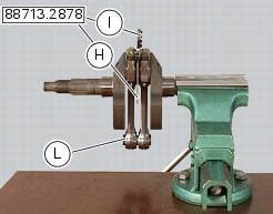
Fit the spacer (h) of the tool 88713.2878 Between the connecting rods and take up residual axial clearance with the fork feeler gauge (i) of the tool 88713.2878 Which is available in the following thicknesses: 0.1 Mm - 0.2 Mm - 0.3 Mm.
Temporarily fit the gudgeon pin (l) to align the connecting rods, and then tighten the screws.
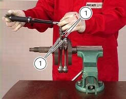
Tighten the screws (1) with a torque wrench and angle reading (degree wheel) in accordance with the procedure described below (observe the same tightening sequence at each step as that of the previous step):
- First torque each screw to a value of 20 nm;
- Now carry out a second tightening stage applying a torque of 35 nm on each screw;
- Now tighten each screw, reading the angle of rotation, to 70 nm, checking that the final angle is between 55 and 75.
Important
If the final angle is less than 55 or greater than 75, repeat the procedure using two new screws.
 Overhaul of the connecting rods
Make the following dimensional checks on the connecting rods:
Clearance with gudgeon pin on assembly.
In the event of excessive wear (sect. 3 - 1.1, Crankshaft), replace the
connecting rod.
...
 Refitting the crankshaft/connecting rod assembly
Install the connecting rod assembly (6) and (2) in the crankcase, carry out
the shimming and crankcase half reassembly
procedure as described in sect. 9 - 9.2, Reassembly of the crankcase halves.
...
Other materials:
Refitting the gear interlock plunger and pawl assembly
On the special screw (3), fit the gear pawl lever (4), orienting it as shown
in the figure, the washer (2) with the square
edge side (d) facing the clutch-side crankcase half, and the spring (1),
positioning it so that the hook end (a) is facing
the gear pawl lever. Locate the hook end (a) of ...
Checking the coolant level
To the specified intervals in the "scheduled maintenance chart" (sect. 4 - 2)
Check the coolant level contained in
the expansion reservoir, on the right side of the vehicle.
The coolant level must be between the max. And min marks on the tank.
If the level is low, top up with the recommende ...
Protective apparel
Always wear a helmet. Most motorcycle accident fatalities
are due to head injuries.
For safety eye protection, gloves, and high top, sturdy boots
should also be worn.
The exhaust system becomes very hot during operation,
never touch the exhaust system. Wear clothing that fully
covers your ...