
Ducati Diavel Service Manual: Reassembly of the cylinder head
The exhaust side can be identified by the three threaded holes on the flange.
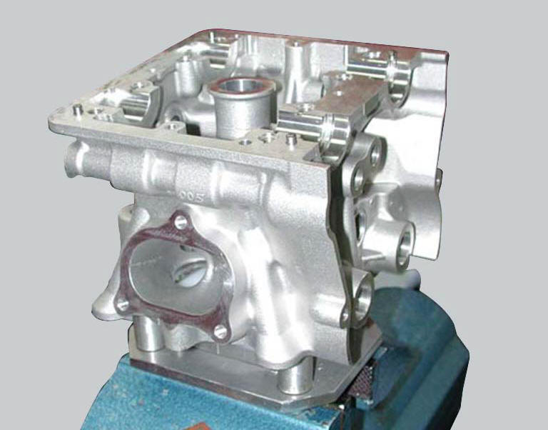
The intake side can be identified by the presence of four threaded holes on the flange.
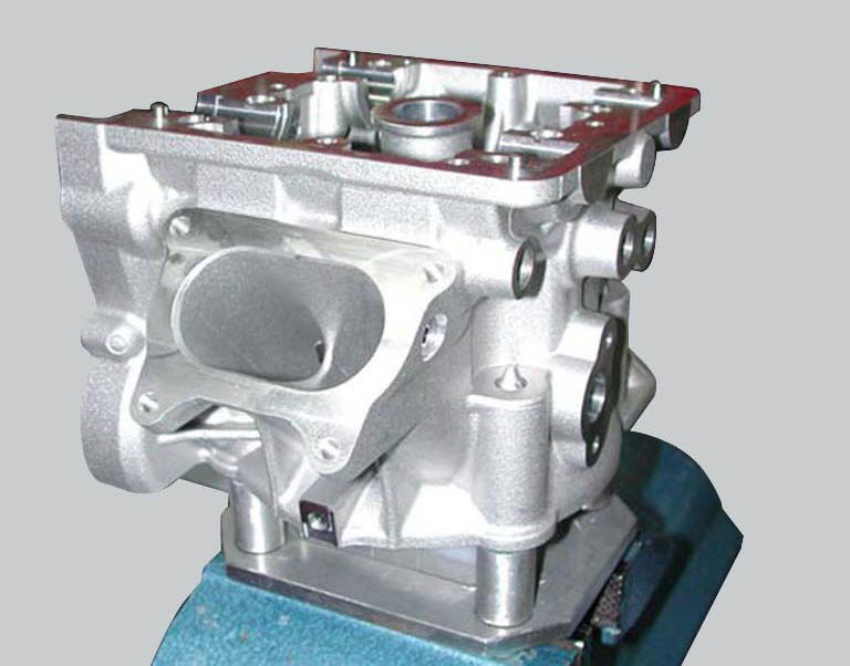
All the photos in this chapter refer to a vertical cylinder head.
Valve guide sealing rings
Position the cylinder head on the appropriate support 88713.2103.
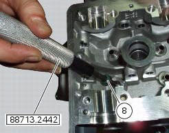
Lubricate the valve guides seal rings (8) with engine oil and insert them from the spring side onto tool 88713.2442.
Fit the end of the tool into the valve guide and use a mallet to tap the sealing rings (8) home into the valve guides.
Reassembly of the closing rocker arms
Check that the rocker arms are not scored or show signs of breakage in the area of contact with the camshaft and shim.
The closing rocker arm shafts are 10 mm in diameter, whereas the opening rocker arm shafts are 9 mm in diameter.
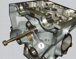
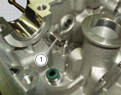
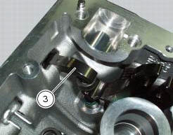
Using an m6 screw, position the closing rocker shaft (1) towards the exhaust side of the cylinder head.
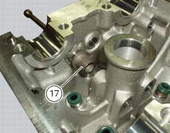
Locate the spacer (17) on the shaft.
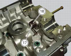
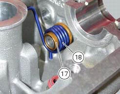
Locate the spring (18) on the spacer (17) as shown, fitting one end of the spring in its seat in the cylinder head.
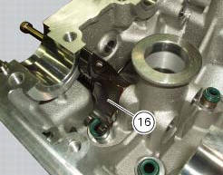
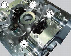
Locate the closing rocker arm (16) into its seat, making sure that the through hole is in line with the closing rocker arm shaft and drive the shaft home.
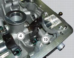
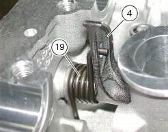
Proceed in a similar manner to install the closing rocker arm (4) with the spring (19).
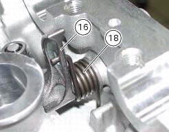
Load the springs (18) and (19) on the closing rocker arms (16) and (4) respectively using the tool 88713.2069.
Proceed to install the closing rocker arms (4) and (16), the springs (24) and (25), the relative pins on the exhaust side in the same manner as described for the intake side.
Note
Always install the closing rocker arms on the exhaust side before those on the intake side.
Warning
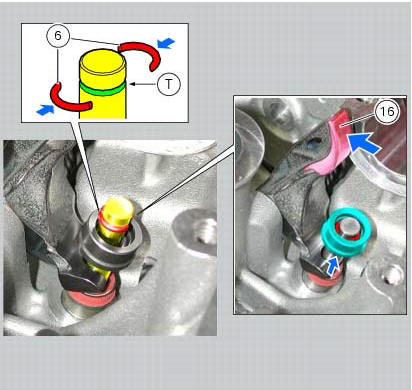
Take care not to damage the shoe of the closing rocker arm with the intake spring during assembly.
Refitting the valves, closing shims and half rings
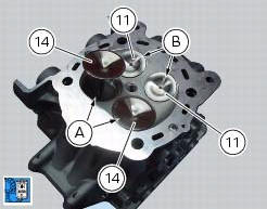
Carefully clean the two intake valve seats (a) and the two exhaust valve seats (b).
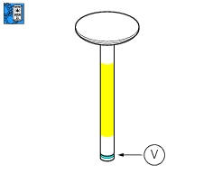
Lubricate the stems of the two intake valves (14) and of the two exhaust valves (11) with engine oil.
Warning
Apply engine oil to the valve stems, however only in the area shown, making sure not to smear the grooves (v).
Install the valves in respective seats in the cylinder head.
Hold
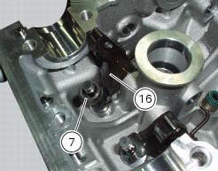
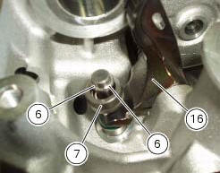
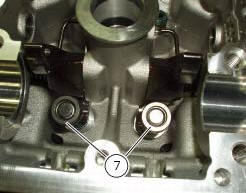
Hold the closing rocker arm (16) pushed downwards and fit the closing shim (7) on the valve stem up to reach the rocker arm. If using the old cylinder head, start by fitting the original shim.
Insert the new half rings (6) in the valve groove (t) and release the rocker arm to obtain shim (7) internal position. Turn the closing rocker arm (16), and compress the spring as much as possible while holding the valve, the shim and the half rings in the valve closed position. Release the rocker arm with a rapid motion, so that the half rings seat in the shim.
Repeat the procedure with the opposite valve and check that the top of the valve stem is aligned with the surface of the shim (7); if it is not, repeat the half ring installation procedure.
Install the closing shims on the intake valves (14) using the method described above for the exhaust valves.
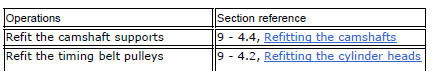
Refit the timing shafts (sect. 9 - 4.4, Refitting the camshafts) to check the valve clearance when closed (sect. 9 - 4.1, Checking and adjusting the valve clearances).
Refitting the opening shims and opening rocker arms
Using an m6 screw, position the opening rocker arm shaft (2) (diameter 9 mm).
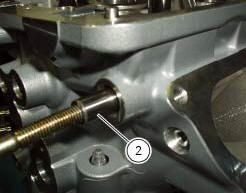
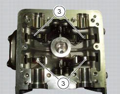
Locate the opening rocker arm (3) and drive the shaft home.
Install the four rocker arms (3) in the manner described above.
Raise the opening rocker arm (3) and install the opening shim (5) so it seats against the valve stem.
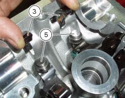
Release the rocker arm so that it rests against the shim.
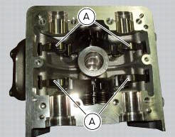
Ensure the shim is correctly seated by lightly tapping the rocker arm shoe (a) with plastic mallet.
Refit the timing shafts (sect. 9 - 4.4, Refitting the camshafts) to check the valve clearance when open (sect. 9 - 4.1, Checking and adjusting the valve clearances).
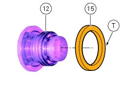
Insert the gaskets (15) on the plugs (12), orienting them (preferably) with the square edge side (t) facing the cylinder head.
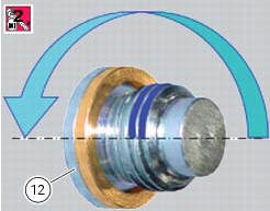
Apply prescribed threadlocker on the plug threads (12): apply the product on the first two plug threads, spreading it for the half circumference (about 180).
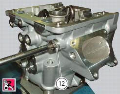
Tighten the plugs to a torque of 15 nm (min. 14 Nm - max. 16 Nm) (sect. 3 - 3, Engine torque settings).
Note
After tightening, remove any excess of product.
 Overhaul of cylinder head components
Cylinder heads
Remove any carbon deposits from the combustion chamber and its ducts.
Remove any scale from the coolant ducts.
Check for cracking and inspect the sealing surfaces for scoring, ri ...
 Refitting the cylinder head assemblies
Warning
To prevent oil leaks past the contact area between cylinders and
crankcase, each time the head is removed, cylinder and
piston must be removed as well to clean the mating faces of crankcas ...
Other materials:
Refitting the camshafts
If the stud bolts (2) were removed, apply the recommended threadlocker to the
short end of the stud bolts (2), i.E. The
end that is to be screwed into the cylinder head. Tighten the stud bolts (2) to
a torque of 10 nm (min. 9 Nm - max. 11
Nm) (sect. 3 - 3, Engine torque settings).
Check t ...
Removal of the steering head components
Note
All parts fitted to the top and bottom yokes, including the wiring and
control cables, can remain on the motorcycle
provided they do not hinder the following operations.
Loosen the screws (19) securing the supports (21) and (23) of splashguard
(22) to the air conveyors (t).
...
Inspection of the gear selector drum
Use a gauge to measure the clearance between fork pin and the slot on the
selector drum.
If the service limit is exceeded, determine which part must be replaced by
comparing these dimensions with those of new
components (sect. 3 - 1.1, Gearbox).
Also check the wear on the drum support pin ...