
Ducati Diavel Service Manual: Refitting the timing belt driveshaft pulleys
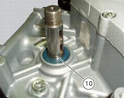
To fit the circlip (10) in the driveshaft seat, use the tool code 88713.2834.
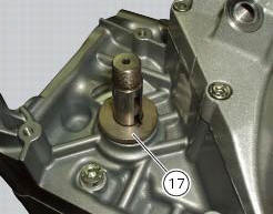
Install the inner spacer (17) on the driveshaft, taking care to align the notch in the spacer with the slot for the woodruff key.
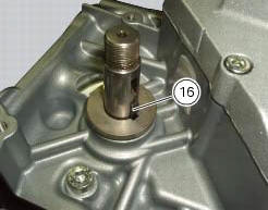
Fit the first woodruff key (16) on the timing belt driveshaft.
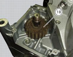
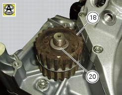
Locate the inner pulley (18).
Refit the second tongue (16) and the washer (19).
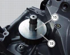
Locate the outer pulley (18) and the spacer (20).
Apply the recommended grease to the threads on the end of the driveshaft.
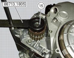
Fit the nut (15).
Important
To prevent the nuts working loose and consequent serious engine damage, always use new self-locking nuts on all the timing belt pulleys on reassembly.
Lock rotation of the pulleys by means of the tool part no. 88713.1805 And, using the insert supplied with the wrench together with a torque wrench, tighten the self-locking nut to the torque of 71 nm (min. 64 Nm - max. 78 Nm) (sect. 3 - 3, Engine torque settings).
 Removing the timing belt driveshaft pulleys
Use the tool code 88713.1805 To hold the driving pulley on the engine
crankcase against rotation.
Important
If this operation is carried out with the engine installed in the frame,
hold the driv ...
 Refitting the idler and tensioner pulley mounting studs
Apply the recommended threadlocker to the threads of the studs.
Insert the tensioner pins (12) on the cylinder heads, and tighten them using the
tool code 88713.1821.
Tighten the tensioner pin ...
Other materials:
Starter motor
Power:
0.7 Kw/12 v
Direction of rotation:
counter clockwise viewed from power take-off side.
The starter motor is highly compact and reliable and therefore rarely gives
any type of problem. In case of troubles,
ensure that the starter motor cable terminal is properly tightened under the n ...
Dashboard
Note
The dashboard is supplied as a single component; its internal components
cannot be renewed separately.
Important
Whenever the dashboard is renewed, the ignition key programming procedure
must be repeated.
Loosen the nuts (2) to remove the master dashboard (1) from its seat and
disconn ...
Riding style function (riding style change)
This function changes the motorcycle riding style.
Each riding style is associated with a different intervention
level of the traction control (dtc - ducati traction control)
and different engine power and output.
To change the motorcycle riding mode, press the reset
button once (12, fig. 1 ...