
Ducati Diavel Service Manual: Removal of the tool tray
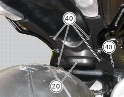
To remove the tool tray unit from the lateral footrests, loosen the screws (40) and remove the splashguard (20).
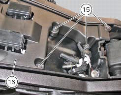
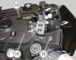
Undo the screws (15) and remove the cover (16).
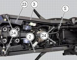
Move the wiring branch from the seat (s) on the tool tray.
Loosen the screws (24) to remove the tool tray unit (23) from the lateral brackets (2) and (3).
 Disassembly of structural components and the frame
Before carrying out dimensional checks on the frame, you must remove all the
superstructures fitted, referring to the
removal procedures outlined in the sections of this manual.
The rear subfram ...
 Removing the frame and the lateral footrests
Loosen the two special screws (6) to separate the frame (1) from the lateral
brackets (2) and (3).
On the left side of the vehicle block retaining pins (9) and loosen the nuts (8)
on the right ...
Other materials:
Gear indicator display on dashboard shows dashes, engaged gear not displayed
correctly, idle speed irregular
with gearbox in neutral
Fault codes
Dds: gear sensor diagnosis -> short circuit to ground or open circuit (s.C.
Gnd or c.O.) - Short circuit to vdc (s.C. Vdc)
- congruence (generic error - signal not correct).
Dashboard: the error "gear sensor" is shown on the service display. The eobd
warning light activates.
...
Oxygen sensors
Introduction
An on-off type oxygen sensor (in normal operating conditions, the voltage
generated by the sensors switches between a
value close to 1v and a value close to 0v) is mounted on each of the exhaust
manifold of the diavel.
Each oxygen sensor has its own internal heater, which recei ...
Refitting the tail light
Fit the spacers with collar (3) into the rear vibration dampers (2) located
on the gloves compartment (23).
Note
Two spacers (3) must be inserted inside and outside on the right side and
two spacers (3) must be inserted inside and
outside on the left side.
Insert the split vibration damp ...