
Ducati Diavel Service Manual: Reassembly of the gearbox shafts
Figure 1 shows all the parts to be reassembled on the gearbox primary shaft (2), with the calculated end shims (1) and (11) (sec. 9 - 9.2, Reassembly of the crankcase halves).
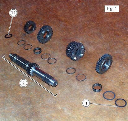
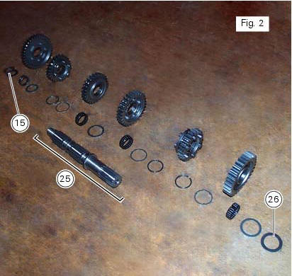
Figure 2 shows all the parts to be installed on the gearbox secondary shaft (25), with calculated end shims (15) and (26) (sec. 9 - 9.2, Reassembly of the crankcase halves).
Reassemble the gears on the gearbox shafts by reversing the disassembly procedure.
Take particular care when installing the idler gears. The assembly of the 3rd and 4th speed gears and the relative fixing components on the secondary shaft is given as an example.
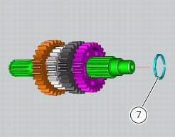
Fit the circlip (7), checking that it is fully inserted into its groove on the shaft. Push the circlip into position with a suitable size tubular drift.
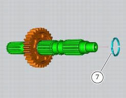
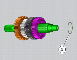
Slide the washer with three internal points (6) over the shaft until it locates against the circlip you have just fitted.
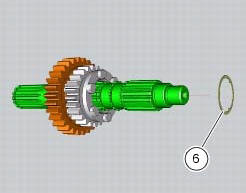
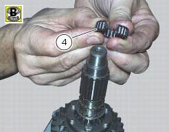
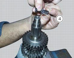
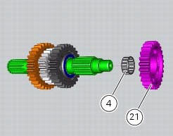
To fit the needle roller cage (4) onto the shaft, first lubricate it with plenty of grease (of recommended type) and then open it slightly to make it easier to slide on to the shaft.
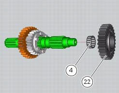
Fit the 3rd speed gear (22).
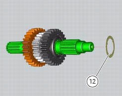
Fit on the gear the three-pointed washer (12), which can be distinguished from its counterpart (6) by its bigger outside diameter.
Fit another needle roller cage (4) using the method already described.
Fit the 4th speed gear (21).
Fit another safety washer (6) and another circlip (7) into the shaft. Push it inside its seat using the previously used pad.
 Inspection of the gear selector drum
Use a gauge to measure the clearance between fork pin and the slot on the
selector drum.
If the service limit is exceeded, determine which part must be replaced by
comparing these dimensions wi ...
 Reassembly of the gearbox
To refit the gearbox components follow the procedure under sect. 9 - 9.2,
Reassembly of the crankcase halves, relating to
reassembly of the engine crankcase.
As a final practical test, ensure th ...
Other materials:
How to switch the dashboard on
The dashboard may switched on either from the on/off switch on the handlebar
or from the button on the hands free
system.
With the engine off, the on/off switch is turned to "run off".
With the motorcycle and dashboard off, the on/off switch is turned to "run
off".
To switch the dash ...
Throttle valve operation engine
Introduction
The electric motor actuating the throttle valve for the vertical cylinder is
mounted on the throttle body of the diavel, while
a link rod connects the vertical cylinder throttle valve to the horizontal
cylinder throttle valve. In the electric motor, the
throttle valve position se ...
Removal of the gearbox assembly
Withdraw the selector fork shafts (30).
Move the forks (28) and (29) to disengage them from the slots in the selector
drum (14).
Withdraw the selector drum (16) taking care not to lose shims (31) and (27)
mounted on the shaft. Note that the
positions of the shims must not be inverte ...